
Filters


NTS8610
Advanced SyncPro: IEC61850-3 HV & IEEE 1613 Certified NTP Server & IEEE 1588 PTP Grandmaster
- IEC61850-3 HV & IEEE 1613 Certified NTP Server & IEEE 1588 PTP Grandmaster
- -40 to +85 °C Operating Temperature, IP40 Protection, and Up to 5100 m Altitude
- MIL-STD-810F Certified for Environmental and Transportation Reliability
- Dual Hot Swappable Power Modules with Wide Power Input Voltage Range
- Full Redundancy Across Power, System, Network, and Link Layers
- <40 ns PRTC-B/PTP, <50 μs NTP Accuracy, Calnex Verified
- Excellent Holdover Performance: <0.5 μs/8 Hours / <72 μs/7 Days
- Supports Power, Telecom, AVBTSN and Enterprise Profiles
- Four Ethernet Ports: Two PTP-Capable Combo Ports, All Four NTP-Capable
- Dual Media Combo Ports Enable Cost-Effective Copper/Fiber Deployment
- Supports Multi-Constellation GNSS with Anti-Jamming and Anti-Spoofing
- Optional Multi-Band GNSS SKU with OSNMA and Up to 4 Concurrent Constellations
- Antenna Fault Detection and Protection: Short Circuit and Disconnection
- Configurable IRIG-B (TTL, Fiber, AM, RS-485), and PPS Outputs
- Built-in 40×2 LCM for Display and Configuration
- Streamlined Cable Management with Rear-Facing Connections
- Standard 5-Year Warranty, Upgradeable to 10 Years
 |
IEC 61850-3 HV & IEEE 1613 Certified NTP/PTP Grandmaster with -40 to +85 °C Operating Temperature With an operating temperature range of -40 to +85 °C, and IEC 61850-3 HV and IEEE 1613 offering up to four times the EMC protection compared to rugged industrial-grade standards, the NTS8610 is engineered to operate reliably in environments exposed to electrical noise, temperature extremes, and radiated disturbances—ensuring uninterrupted performance and high system availability. The NTS8610 NTP Server and IEEE 1588 PTP Grandmaster is the world’s first solution fully certified to both IEC 61850-3 HV and IEEE 1613 standards, delivering exceptional resilience and precision in demanding applications such as power substations, telecommunications networks, automation systems, and enterprise infrastructure. |
 |
High Precision Timing Rigorously tested by Calnex Solutions, a leader in network synchronization testing, the NTS8610 series delivers exceptional time precision, ensuring your power applications’ synchronization needs are met with the highest standards of accuracy. Featuring proven PRTC-B accuracy within 40 ns, IEEE 1588 PTP accuracy within 40 ns, and NTP accuracy within 50 μs, this Grandmaster guarantees precise time distribution across your network. |
 |
Superior Holdover Performance Holdover performance is critical to ensure uninterrupted and accurate time synchronization during loss of the primary time source. The NTS8610 series offers exceptional holdover stability, with a drift of less than 0.5 μs over 8 hours, and approximately 72 μs over 7 days, as validated by Calnex Solutions. When entering holdover mode, the system intelligently adjusts protocol attributes according to the active time profile (e.g., Power, Telecom), and proactively issues notifications via alarms and syslog to alert operators. |
 |
Versatile Profile Support The Grandmaster supports a wide range of IEEE 1588 PTP profiles, making it suitable for deployment in power, telecom, AVB/TSN, and enterprise networks. For power utilities, it complies with IEEE C37.238-2011, C37.238-2017, and IEC/IEEE 61850-9-3:2016. Telecom synchronization is supported through ITU-T G.8265.1, G.8275.1, and G.8275.2 profiles. IEEE 802.1AS is also supported for time-sensitive networking in industrial and media environments. The Enterprise profile ensures interoperability across standard IT infrastructures. In addition, the Grandmaster supports SyncE for enhanced frequency stability in telecom applications. |
 |
GNSS Vulnerability Mitigation and Antenna Protection NTS8610 offers enhanced robustness and resilience against jamming and spoofing attacks. By receiving signals from multiple constellations on single or multiple bands for cross-verification, the system can detect spoofing attempts and switch to holdover mode if necessary. The Grandmaster also features comprehensive antenna vulnerability mitigation, detecting short and disconnected antennas to maintain system integrity. For added protection, a surge protector is available for purchase, safeguarding your equipment from electrical surges and ensuring the reliability of your timing infrastructure. |
 |
Comprehensive Redundancy System redundancy is ensured through clustering, featuring IEC 62439-3 Parallel Redundancy Protocol (PRP) to provide network redundancy without data loss or downtime. Link redundancy is achieved via bonding and auto-failover functionality of combo ports, delivering resilient connectivity. Additionally, the NTS8610 series offers power redundancy with dual hot-swappable, detectable power modules supporting a wide input voltage range to safeguard against power failures. |
 |
Flexible Timing Input/Output Modulated IRIG-B is ideal for long-distance transmission due to its resistance to signal degradation and compatibility with legacy equipment. Demodulated IRIG-B, available in TTL or RS-485 formats, offers higher precision, with IRIG-B RS-485 supporting distances up to 1200 meters. PPS outputs are crucial timing signals in modern IEC 61850 power applications, providing precise synchronization essential for various grid operations. The NTS8610 series supports up to two selectable synchronization modules, offering options such as IRIG-B (TTL, AM, Fiber, RS-485) and 1-PPS waveform input or output, with up to seven configurable channels. Additionally, IRIG-B RS-485 can be extended over long distances using the ATOP SF63 serial-to-fiber converter via fiber-optic cable. |
 |
Ensuring Precision with Comprehensive Delay Compensation Compensation for antenna delay is essential because long antenna cables can introduce timing errors that affect the accuracy of synchronized operations. Similarly, output delay compensation for signals such as IRIG-B and PPS is vital, especially in systems with multiple IEDs connected. It is much easier and more efficient to compensate for cable delays at the Grandmaster level rather than at each individual IED, as not all IEDs support delay compensation. Handling these adjustments centrally at the Grandmaster guarantees that all connected devices operate in perfect sync, optimizing the performance and coordination of critical substation operations. |
 |
Trusted GNSS Timing with OSNMA NTS8610M supports Galileo OSNMA, a feature that helps verify whether received Galileo navigation messages are genuine. In simple terms, it helps the device check that the GNSS timing data comes from a real source and has not been tampered with. This helps detect possible spoofing attempts and improves the trust, reliability, and integrity of time synchronization for critical infrastructure applications. |
APPLICATION CASE
IEEE 1588 in Power Networks: Precision Time Synchronization and Time RedundancyTwo NTS8610 units in the station layer determine the Active and Backup GMC through BMCA. The Active GMC synchronizes to both GPS and GNSS satellite systems and transmits via IEC 62439-3 PRP to two power domains composed of PRP and HSR networks. According to IEC 61850-9-3 and IEEE C37.238-2017, the total end-to-end budget is 1us, with GMC being 250ns. The NTS8610 achieves superior accuracy of <40ns, reserving more budget for other devices. For early MU devices that rely on 1PPS or IRIG-B for synchronization, the NTS8610 offers 1PPS, IRIG-TTL, IRIG-B AM, IRIG-B RS-485, and RS-485 to fiber-optics by SF-63 for long-distance transmission and delay compensation.
The HSR network provides zero-packet-loss redundancy but also increases latency. Devices in the process layer require more precise timing. When the end-to-end budget cannot be met, a GMC must be deployed to aid in accurate timing for critical devices. The NTS8610, certified to IEC61850-3 HV & IEEE 1613, operates reliably in harsh process layer environments, providing precise synchronization.
In addition to the NTS8610, our timing solution for power substations also includes BC or TC of RHG9728 and RHG9528, P-Delay TC of EH9711, HSR Redbox, and Quadbox of RGB700X. Check our website for more detailed information on these products.

CONNECTORS

| Technical Specifications | |
|---|---|
| Model Name | NTS8610 & NTS8610M Series (See ordering information) |
| Single Band (NTS8610 Series) - GNSS Receiver Specifications | ||
|---|---|---|
| GNSS Input ports | 1x GNSS Input; TNC (F) - active Antenna | |
| GNSS Module specific Information | Multi-Constellation Supported: GPS L1, GLONASS L1, BeiDou B1, Galileo E1 Maximum Concurrent Constellations: 3 Leap Second: Supported Sensitivity for GPS: • Tracking: -166 dBm • Reacquisition: -160 dBm • Cold Start: -148 dBm • Hot Start: -160 dBm |
|
| Acquisition Times | Cold Start: <45 seconds Warm Start: < 7 seconds |
|
| Antenna Requirements | 3.3 V, <50 mA Minimum gain=5dB; Maximum gain + Cable Attenuation ≤ 40dB |
|
| GNSS Vulnerability Mitigation | Jamming | Support Detection, Warning and Switch to OCXO Holdover |
| Spoofing | Support Detection, Warning and Switch to OCXO Holdover (GNSS Antenna Only) | |
| Antenna Vulnerability Mitigation | Antenna Cable Short | Support Detection, Warning and Switch to OCXO Holdover Mode |
| Antenna Disconnection | Support Detection, Warning and Switch to OCXO Holdover Mode | |
| Multiple Band (NTS8610M Series) - GNSS Receiver Specifications | ||
|---|---|---|
| GNSS Input ports | 1x GNSS Input; TNC (F) - active Antenna | |
| GNSS Module specific Information | Multi-Constellation Supported: GPS: L1C/A, L2C or L5 Galileo: E1, E5a or E5b BeiDou: B1I, B2I or B2a GLONASS: L1OF NavIC: L5 Maximum Concurrent Constellation: 4 Leap Second: Supported Sensitivity for GPS + GLONASS + Galieo + BeiDou • Tracking: -167 dBm • Reacquisition: -160 dBm • Cold Start: -148 dBm • Hot Start: -157 dBm |
|
| Acquisition Times | Cold Start: <24 seconds Warm Start: <2 seconds |
|
| Antenna Requirements | 3.3 V, <50 mA Minimum gain = 6dB; Maximum gain + Cable Attenuation ≤ 30dB |
|
| GNSS Vulnerability Mitigation | Jamming | Support Detection, Warning and Switch to OCXO Holdover |
| Spoofing | Support Detection, Warning and Switch to OCXO Holdover (GNSS Antenna Only) | |
| Antenna Vulnerability Mitigation | Antenna Cable Short | Support Detection, Warning and Switch to OCXO Holdover Mode |
| Antenna Disconnection | Support Detection, Warning and Switch to OCXO Holdover Mode | |
| Antenna specification (Accessories) | |
|---|---|
| GNSS Antenna (59902521G) | GNSS Receiver: GPS L1, GLONASS L1, BeiDou B1, Galileo E1 LNA Gain: 40dB min Weather-Proof Housing: IP69K Operating and Storage Temperature: -40°C - 85°C ESD: ±15KV Air Discharge Mechanical Size: 66.5 mm dia. x 21 mm H MIL-STD-810F Supply Voltage Range: 2.5 to 16VDC |
| GPS Antenna (59902531G) | GNSS receiver: GPS L1, Galileo E1 LNA Gain: 40dB min Weather-Proof Housing: IP69K Operating and Storage Temperature: -40°C - 85°C ESD: ±15KV Air Discharge Mechanical size: 66.5 mm dia. x 21 mm H MIL-STD-810F Supply Voltage Range: 2.5 to 16VDC |
| Anti-Jamming GNSS Antenna (59902661G) |
GNSS Receiver: GPS L1, GLONASS L1, BeiDou B1, Galileo E1 LNA Gain: 40dB typ. Weather-Proof Housing: IPX7 Operating and Storage Temperature: -40°C - 85°C ESD: ±15KV Air Discharge Mechanical Size: 100 mm dia. x 102 mm H MIL-STD-810F Supply Voltage Range: 2.5 to 16VDC |
| Dual-band GNSS Antenna (59903031G) For NTS8610M series |
Supports the most widely used L1 + L5 bands, providing a cost-effective option GNSS Receiver: GPS: L1C/A or L5 Galileo: E1, E5a or E5b BeiDou: B1I or B2a GLONASS: L1OF NavIC: L5 LNA Gain: 40 dB min Weather-Proof Housing: IP69K Operating and Storage Temperature: -40°C - 85°C ESD: ±15KV Air Discharge Mechanical Size: 66.5 mm dia. x 21 mm H MIL-STD-810F Supply Voltage Range: 2.5 to 16VDC |
| Multi-band GNSS Antenna (59902851G) For NTS8610M series |
Suitable for full-band applications or projects requiring L2/L5 flexibility. GNSS Receiver: GPS: L1C/A, L2C or L5 Galileo: E1, E5a or E5b BeiDou: B1I, B2I or B2a GLONASS: L1OF NavIC: L5 LNA Gain: 37dB min Weather-Proof Housing: IP69K Operating and Storage Temperature: -40°C - 85°C ESD: ±15KV Air Discharge Mechanical Size: 66.5 mm dia. x 21 mm H MIL-STD-810F Supply Voltage Range: 2.5 to 16VDC |
| Anti-Jamming Multi-band GNSS Antenna (59903021G) For NTS8610M series |
GNSS Receiver: GPS: L1C/A, L2C or L5 Galileo: E1 or E5b BeiDou: B1I, B2I or B2a GLONASS: L1OF NavIC: L5 LNA Gain: 40dB min Weather-Proof Housing: IPX9K Operating and Storage Temperature: -40°C - 85°C ESD: ±15KV Air Discharge Mechanical Size: 90 mm dia. x 180 mm H MIL-STD-810F Supply Voltage Range: 2.5 to 16VDC |
| Maximum Antenna Cable Length | Antenna cable: Without amplifier: LMR-400: 150M CFD-240: 100M CFD-200: 50M RG58A/U: 25M With Amplifier: LMR-400: 250M CFD-240: 100M CFD-200: 80M RG58A/U: 50M |
| Maximum Sync-Out Cable Length | RG58 A/U Sync-Out cable: 1PPS, IRIG-B TTL: 150M IRIG-B AM: 150M @ 1K impedance, 300M @ 10K impedance IRIG-B RS485: 1200M IRIG-B Fiber TTL: 1500M IRIG-B RS-485 with SF63 Fiber optic 2KM |
| Proven Clock Accuracy (Relative to UTC) | |
|---|---|
| 1PPS | ±40 ns Peak *1 |
| Demodulated IRIG-B | ±40 ns Peak *1 |
| Modulated IRIG-B AM | ±1 μs Peak *1 |
| RS-485 IRIG-B | ±100 ns Peak *1 |
| PTP Timestamp | ±40 ns Peak *1 |
| NTP Timestamp | ±50 us Peak , ±40 us Average *1 |
| Holdover accuracy - OCXO | <0.5 us / 8 hours / <72 us / 7 days *2 |
| *1. Device locked to satellites for at least 24 hours. *2. Device locked to satellites for at least 48 hours before holdover |
| Network Interface | |
|---|---|
| Ethernet Standards | IEEE 802.3 10BaseT IEEE 802.3u 100BaseT(X) IEEE 802.3ab for 1000BaseT(X) IEEE 802.3u for 100Base-FX IEEE 802.3z for 1000Base-X |
| Gigabit Ethernet Ports | Two Combo ports, 2x 10/100/1000BASE-T(X) RJ45 or 2x 100/1000 Base-X SFP Support Synchronous Ethernet (SyncE) per ITU-T G.8261 ITU-T, G.8262 and G.8264 ESMC), PTP-Capable and NTP-Capable |
| Management Port | 2 x 10/100 BASE-T(X) RJ45, NTP-Capable |
| LCD Display & Control Buttons | |
|---|---|
| LCD Spec | Character Display LCD 40x2 5x8 Dots Includes Cursor LCD Operating Temperature Range: -20°C to 70°C LCD Over-Temperature Protection |
| Control Buttons | Up, Down, Left, Right, Menu, Enter, Back |
| I/O | |
|---|---|
| Console | 1x DB9 Serial Console Port |
| SD slot | 1x micro-SD slot |
| Relay - Alarm Contact | Three Pins Relay with NC, NO and GND. Rated Operational Voltage: 24-250 VDC Continuous carrier: 3 A max. 75VA max Dropout Time: ≤ 6 ms typical Pickup time: ≤ 8 ms |
| Sync Module – S1 (Applied for NTS8610 & NTS8610M) | |
|---|---|
| Sync1 ~ Sync2 | Two configurable output channels (coaxial BNC (F) connector): 1. 1PPS/PPM/PPH Output (Square Wave, configurable pulse width) 2. IRIG-B TTL Output (Support IEEE 1344 and C37.118.1) 3. AFNOR French Time Code Output 4. ASCII Timestamp Output* |
| Sync Module – S2 (Applied for NTS8610-S2 & NTS8610M-S2) | |
|---|---|
| Sync1 ~ Sync2 | Two configurable output channels (coaxial BNC (F) connector): 1. 1PPS/PPM/PPH Output (Square Wave, configurable pulse width) 2. IRIG-B TTL Output (Support IEEE 1344 and C37.118.1) 3. AFNOR French Time Code Output 4. ASCII Timestamp Output* |
| Sync3 ~ Sync5 | Three configurable output channels (Sync 3 - Sync 5, coaxial BNC (F) connector): 1. 1PPS/PPM/PPH Output (Square Wave, configurable pulse width 2. IRIG-B TTL B000~B007 Output (Support IEEE 1344 and C37.118.1) 3. IRIG-B AM B120~B127 Output (Support IEEE 1344 and C37.118.1) 4. AFNOR French Time Code 5. ASCII Timestamp Output* |
| Sync6 | One configurable output channel (Sync 6, TB3 connector): 1. IRIG-B RS-485 B000~B007 Output (Support IEEE 1344 and C37.118.1) 2. AFNOR French Time Code Output |
| Sync Module – S3 (Applied for NTS8610-S3 & NTS8610M-S3) | |
|---|---|
| Sync1 ~ Sync2 | Two configurable output channels (coaxial BNC (F) connector): 1. 1PPS/PPM/PPH Output (Square Wave, configurable pulse width) 2. IRIG-B TTL Output (Support IEEE 1344 and C37.118.1) 3. AFNOR French Time Code Output 4. ASCII Timestamp Output* |
| Sync3 | One configurable output channel (Sync 3, coaxial BNC (F) connector): 1. 1PPS/PPM/PPH Output (Square Wave, configurable pulse width) 2. IRIG-B TTL B000~B007 Output (Support IEEE 1344 and C37.118.1) 3. IRIG-B AM B120~B127 Output (Support IEEE 1344 and C37.118.1) 4. AFNOR French Time Code 5. ASCII Timestamp Output* |
| Sync4 | One configurable input channel (coaxial BNC (F) connector): 1. IRIG-B TTL B000~B007 Input (Support IEEE 1344 and C37.118.1) 2. 1PPS input 3. AFNOR French Time Code TTL Input |
| Sync5 | One configurable modulated input channel (coaxial BNC (F) connector): 1. IRIG-B AM B120~B127 Input (Support IEEE 1344 and C37.118.1) 2. Modulated AFNOR French Time Code Input |
| Sync6 | One configurable input/output channel (Sync 6, TB3 connector): 1. IRIG-B RS-485 B000~B007 Input (Support IEEE 1344 and C37.118.1) 2. IRIG-B RS-485 B000~B007 Output (Support IEEE 1344 and C37.118.1) 3. AFNOR French Time Code RS-485 Input 4. AFNOR French Time Code RS-485 Output |
| Sync7 | One configurable output channel (ST (F) connector): 1. 1PPS/PPM/PPH Output (Square Wave, configurable pulse width) 2. IRIG-B TTL Output (Support IEEE 1344 and C37.118.1) 3. AFNOR French Time Code Output 4. ASCII Timestamp Output* |
* Upon customer request
| Electrical Input/ Output Drive Levels | |
|---|---|
| 1PPS/IRIG-B TTL Output | 5VDC 20 mA TTL compliant |
| Modulated IRIG-B Output | 5Vp-p, 3.3:1 ratio, AM, Sinewave |
| 1PPS/IRIG-B TTL Input | 5VDC HCMOS, >2.0V High <0.8V Low |
| Modulated IRIG-B Input | 1Vp-p to 8 Vp-p, ratio 3.3:1, AM |
| IRIG-B Fiber TTL | 820nm, Different fiber size: 50/125um, 62.5/125um, Output Driver Typ. 13.1uW |
| IRIG-B RS485 Input/Output | ±5 VDC IRIG-B Half-Duplex; 32 Transceivers Max. a bus |
| Frequency | |
|---|---|
| Oscillator | Advanced managed OCXO, with temperature drifting compensation |
| IEEE1588 Profiles | |
|---|---|
| Default | IEEE 1588V2 (PTPv2) Default UDP (IEEE1588-2008 Annex D and J) Default 802.3 (IEEE1588-2008 Annex F and J) |
| Power | IEC/IEEE61850-9-3-2016 Power Utility Profile IEEE C37.238-2011 Power Profile, with VLAN support IEEE C37.238-2017 Power Profile, with VLAN support |
| Telecom | ITUT-G.8265.1 Frequency ITUT-G.8275.1 Phase/Time ITUT-G.8275.2 Phase/Time |
| AVBTSN | 802.1AS Profile |
| Enterprise | Enterprise Profile |
| Media Broadcast | AES67 Media Profile (Ready) SMPTE ST 2059-2 (In Development Plan) |
| System Modes | |
|---|---|
| GNSS Locked Mode | Synchronizes time with GNSS signals for high accuracy |
| Holdover Mode | Maintains time using the OCXO clock after GNSS is unavailable |
| Free Run Mode | Operates independently using RTC as the time source along with the OCXO clock |
| Boundary Clock Mode | Synchronizes to an upstream PTP master and distributes PTP time downstream. |
| APTS Mode | Provides alternate PTP time-source support when GNSS is unavailable. S3 models can also use external timing inputs such as IRIG-B and PPS. |
| Functions & Protocols | ||
|---|---|---|
| Protocols | Network Synchronization | RFC 1119 (NTPv2) Server RFC 1305 (NTPv3) Server RFC 5905 (NTPv4) Server RFC 1769 (SNTPv3) Server RFC 2030 (SNTPv4) Server |
| Network Protocols | VLAN (IEEE 802.1q) filtering/tagging IEEE 802.1p QoS DSCP Pv4, IPv6 TCP, UDP DHCP Client TACAS+/ RADIUS |
|
| Redundancy | Devices Clustering (NTP Only) PRP (IEC 62439-3) Bonding – Active & Backup Bonding -- LACP Combo Ports |
|
| Management | HTTP, HTTPS SNMP v1/v2,v3 SSH/Telnet (CLI), could be enabled/disabled Console CLI Estimated Time Accuracy GNSS Status Power Status PTP & NTP Status SD/MMC Backup & Restore |
|
| Event & Alarm | Event Log Syslog Relay & Alarm Management SNMP Trap |
|
| Physical Characteristics | |
|---|---|
| Housing | SPCC w/Zinc Plated Body + Aluminum cover IP40 Metal Housing |
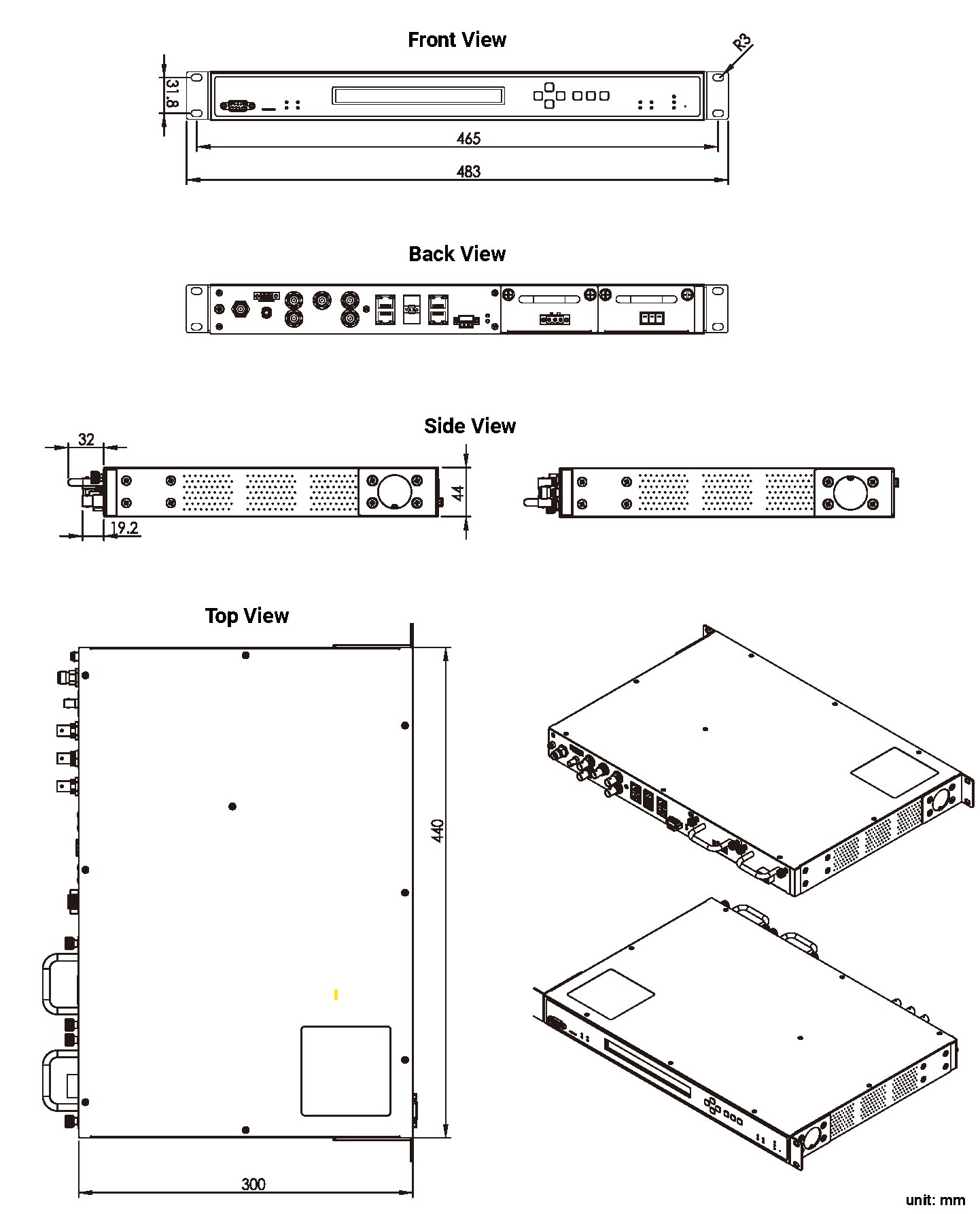
| Dimension (W x H x D) | 440 x 300 x 44 Chassis made of 1 mm SECC Sheet |
| Weight | 3.9 KG Max |
| Installation | 1U Rackmount |
| Power Supply | |
|---|---|
| DC Module | Rated Supply Voltage: ±24 – ±60 VDC Input Voltage Range: ±20 – ±66 VDC |
| AC Module | Rated Supply Voltage: 110 – 240 VAC, 50/60 HZ 110 – 250 VDC Input Voltage Range: 85 – 264 VAC, 50/60 HZ 88 – 300 VDC |
| Power Consumption | Approximately 15 W (Typical) Approximately 20 W (Max) |
| Environmental Limits | |
|---|---|
| Operating Temperature | -40°C to +85°C (-40°F to 185°F) |
| Storage Temperature | -40°C to +85°C (-40°F to 185°F) |
| Operating Altitude | 5100m |
| Ambient Relative Humidity | 5% to 95% (Non-condensing) |
| Regulatory Approvals | |
|---|---|
| Safety | UL 62368-1, CB IEC62368-1/EN62368-1 (Certified Operating Temperature: 75°C), IEC 60255-5 |
| EMC | FCC(EMI): FCC Part 15, Subpart B, Class A CE(EMI): EN 55032, EN 61000-6-4, Class A EN 61000-3-2 (Current Harmonics) EN 61000-3-3 (Voltage Flicker) CE(EMS): EN 55035, EN 61000-6-2 CE(GNSS): EN 303 413. EN 301 489-19 IEC 60255-25, IEC 60255-22-1 |
| Power Automation | IEC 61850-3, IEEE 1613 |
| Test | Item | Value | Level | |
|---|---|---|---|---|
| IEC 61000-4-2 | ESD | Contact Discharge Air Discharge |
±8KV ±15KV |
4 4 |
| IEC 61000-4-3 | RS | Enclosure Port | 10(V/m), 80-3000MHz 20(V/m), 80-1000MHz |
3 |
| IEC 61000-4-4 | EFT | AC Power Port DC Power Port Signal Port |
±4.0 kV ±4.0 kV ±4.0 kV |
4 4 Special |
| IEC 61000-4-5 | Surge | AC Power Port AC Power Port C Power Port DC Power Port Signal Port |
Line-to Line±2.0 kV Line-to Earth±4.0 kV Line-to Line±1.0 kV Line-to Earth±2.0 kV Line-to Earth±4.0 kV |
4 4 4 3 4 |
| IEC 61000-4-6 | CS | 0.15-80MHz | 10V rms 0.15-80MHz, 80% AM | 3 |
| IEC 61000-4-8 | PFMF | (Enclosure) | 100A/m continuous, 1000A/m (3s) | 5 |
| IEC 61000-4-11 | DIP | AC Power Port | 30% Reduction (Voltage Dips), 1 Period 60% Reduction (Voltage Dips), 50 Period 100%, Reduction (Voltage Interruptions), 5 Period 100% Reduction (Voltage Interruptions), 50 Period |
- |
| IEC 61000-4-12 | Ring wave immunity | AC Power Port AC Power Port DC Power Port C Power Port Signal Port |
Line-to Line±1.0 kV Line-to Earth±2.0 kV Line-to Line±1.0 kV Line-to Earth±2.0 kV Line-to Earth±4.0 kV |
3 3 3 3 3 |
| IEC 61000-4-16 | Main Frequency Voltage | DC Input Port Signal Port |
30V Continuous, 300V 1s 30V Continuous, 300V 1s |
4 4 |
| IEC 61000-4-17 | Ripple | DC Input Port | 10% of unit | 3 |
| IEC 61000-4-18 | Damped Oscillatory | AC Power Port | 2.5KV common, 1KV differential mode @ 1MHz |
3 |
| Signal Port Telecommunication Port |
2.5KV common, 1KV differential mode @ 1MHz |
3 | ||
| IEC 61000-4-29 | DC Voltage Dips & Interruptions | DC Input Port | 30% Reduction (Voltage Dips): 0.1 sec 60% Reduction (Voltage Dips): 0.1 sec 100% Reduction (Voltage Interruption): 0.05 sec |
- |
| IEC 60255-22-1 | 1 MHz burst immunity | AC Power Port AC Power Port DC Power Port DC Power Port Signal Port |
Line-to Line±1.0 kV Line-to Earth±2.5 kV Line-to Line±1.0 kV Line-to Earth±2.5 kV Line-to Earth±1.0 kV |
- |
| Certification | Standard |
|---|---|
| Shock Drop Vibration | MIL-STD-810G Method 516.5 MIL-STD-810F Method 516.5 MIL-STD-810F Method 514.5 C-1 & C-2 |
| RoHS2 | Yes |
| MTBF | 20 years |
| Warranty | 5 years / Upgradable to 10 years |
DIMENSIONS & LAYOUT
Main core and Modules
| Model Name | Part Number | GNSS Module | Sync Module | Power Modules |
|---|---|---|---|---|
| NTS8610 | 1P1NTS86100001G | Single Band & Multi-Constellation |
S1 | Support Two Hot Swappable Power Modules. 2x NTS8610-AC or 2x NTS8610-DC or 1x NTS8610-DC + 1x NTS8610-AC |
| NTS8610-S2 | 1P1NTS86100002G | S2 | ||
| NTS8610-S3 | 1P1NTS86100003G | S3 | ||
| NTS8610M | 1P1NTS8610M001G | Multi-Bands & Multi-Constellation |
S1 | |
| NTS8610M-S2 | 1P1NTS8610M002G | S2 | ||
| NTS8610M-S3 | 1P1NTS8610M003G | S3 | ||
| NTS8610M (OSNMA) |
1P1NTS8610M004G | Multi-Bands & Multi-Constellation Galileo OSNMA supported* |
S1 | |
| NTS8610M-S2 (OSNMA) |
1P1NTS8610M005G | S2 | ||
| NTS8610M-S3 (OSNMA) |
1P1NTS8610M006G | S3 | ||
| * GLONASS not supported on OSNMA models * Refer to the NTS86X0 Selection Guide for product differences. |
||||
Power Modules
| Model Name | Part Number | Description |
|---|---|---|
| NTS8610-DC | 1P1NTS8610DC01G | Rated Supply Voltage: ±24 – ±60 VDC Input Voltage Range: ±20 – ±66 VDC |
| NTS8610-AC | 1P1NTS8610AC01G | Rated Supply Voltage: 110 – 240 VAC, 50/60 Hz 110 – 250 VDC Input Voltage Range: 85 – 264 VAC, 50/60 Hz 88 – 300 VDC |
Optional Accessories – Antenna, Amplifier, Surge Protector and Mounting Kits
| Model Name | Part Number | Description |
|---|---|---|
| Single Band GNSS Antenna | 59902521G | High Gain Multi-Constellation & Single Band TNC-Female Antenna (See the Antenna Specifications section above for a spec summary) |
| Single Band GPS Antenna | 59902531G | High Gain GPS L1 TNC-Female Antenna (See the Antenna Specifications section above for a spec summary) |
| Anti-Jamming GNSS Antenna | 59902661G | High Gain Multi-Constellation & Single Band TNC-Female Antenna (See the Antenna Specifications section above for a spec summary) |
| Multi Band GNSS Antenna | 59902851G | High Gain Multi-Constellation and Multi-bands TNC-Female Antenna (See the Antenna Specifications section above for a spec summary) |
| Dual Band GNSS Antenna |
59903031G | High Gain Multi-Constellation and Dual-bands TNC-Female Antenna (See the Antenna Specifications section above for a spec summary) |
| Multi Band Anti-Jamming GNSS Antenna |
59903021G | High Gain Anti-Jamming Multi-Constellation and Triple-bands TNC-Female Antenna (See the Antenna Specifications section above for a spec summary) |
| RF Amplifier | 70100000000092G | Inline TNC-Female RF (1559-1610MHz) Amplifier 25dB with Supply Volts 3-10 VDC and 10 mA including One TNC Male to TNC Male adapter |
| Surge Protector | 70100000000093G | SOCAA 4LTJ10TP001 – TNC-Female 10 kA Surge protection device including One TNC Female to TNC Female adapter |
| Advanced Surge Protector | 70100000000094G | Phoenix Contact CN-UB-280DC-BB – N-Type 20 KA Surge protection device including Two N-type Male to TNC Female |
| Mounting Kits | 70100000000095G | The Antenna Mounting Kit Includes an L-bracket, Mount Adapter and Ground Plane. (See NTS8610 User Manual for More Details) |
| TNC M to M Adaptor | 59902971G | TNC Male to Male Adaptor |
| TNC F to F Adaptor | 59902981G | TNC Female to Female Adaptor |
Optional Accessories – Antenna and Sync-Out Cables
| Model Name | Part Number | Description |
|---|---|---|
| Antenna Cable RG58 | Made to Order | TNC-Male to TNC-Male RG58 Antenna Cable. Maximum RG58 Antenna Cable Length: 25m |
| Antenna Cable CFD-200 | Made to Order | TNC-Male to TNC-Male CFD-200 Antenna Cable. Maximum CFD-200 Antenna Cable Length: 50m |
| Antenna Cable CFD-240 | Made to Order | TNC-Male to TNC-Male CFD-240 Antenna Cable. Maximum CFD-240 Antenna Cable Length: 100m |
| Antenna Cable LMR-400 | Made to Order | TNC-Male to TNC-Male LMR-400 Antenna Cable. Maximum LMR-400 Antenna Cable Length: 150m Maximum LMR-400 Antenna Cable Length with RF Amplifier: 250m |
| Sync-Out Cable (IRIG-B/PPS TTL) |
Made to Order | BNC-Male to BNC-Male Custom-Length RG58 A/U Antenna Cable. Specify desired length when ordering. Supports up to 150 m. |
Optional Accessories – SFP Modules
| Model Name | Part Number | Description |
|---|---|---|
| AXFD-1314-0523 | 522AXFD1314001G | SFP Transceiver, 155 Mbps, 1310 nm, multi-mode, 2 km, -40°C to +85°C, DDMI |
| AXFD-1314-0553 | 522AXFD1314011G | SFP Transceiver, 155 Mbps, 1310 nm, single-mode, 30 km, -40°C to +85°C, DDMI |
| AXGD-5854-0513 | 522AXGD5854001G | SFP Transceiver, 1250 Mbps, 850 nm, multi-mode, 550 m, 3.3V, -40°C to +85°C, DDMI |
| AXGD-1354-0523 | 522AXGD1354001G | SFP Transceiver, 1250 Mbps, 1310 nm, multi-mode, 2 km, 3.3V, -40°C to +85°C, DDMI |
| AXGD-1354-0533 | 522AXGD1354011G | SFP Transceiver, 1250 Mbps, 1310 nm, single-mode, 10 km, 3.3V, -40°C to +85°C, DDMI |
| AXGD-3354-0593 | 522AXGD3354001G | SFP Transceiver, 1250 Mbps, 1310 nm, single-mode, 40 km, 3.3V, -40°C to +85°C, DDMI |
Optional Accessories – External Power Adapter and Converter
| Model Name | Part Number | Description |
|---|---|---|
| SDR-75-24 | 50500752240001G | Din-rail Power Supply/T; 88 - 264 VAC/124 - 370 VDC to 24 VDC 3.2 A; 75W |
| SF63 Series | See ATOP SF63 Datasheet | Industrial Serial to Fiber Media Converter for Long Distance Transmission |
Datasheet
| VERSION | NAME | TIME | SIZE | DOWNLOAD |
|---|---|---|---|---|
| v1.2 | NTS8610 Series Datasheet EN | 2026-05-29 | 1.40 MB |
Hardware Installation Guide
| VERSION | NAME | TIME | SIZE | DOWNLOAD |
|---|---|---|---|---|
| v1.0 | NTS8610 Series Hardware Installation Guide | 2025-10-31 | 21.91 MB |
Manual
| VERSION | NAME | TIME | SIZE | DOWNLOAD |
|---|---|---|---|---|
| v1.02 | NTS8610 Series User Manual | 2026-06-01 | 12.21 MB |
Firmware
MIB
STP/DXF drawings
| VERSION | NAME | TIME | SIZE | DOWNLOAD |
|---|---|---|---|---|
| NTS8610 Series STP file | 2025-10-31 | 33.34 MB |
Test reports
Others
| VERSION | NAME | TIME | SIZE | DOWNLOAD |
|---|---|---|---|---|
| v1.0 | GMC Quick Selection Guide | 2026-05-29 | 7.00 MB | |
| v1.1 | GMC Product Selection Guide | 2026-05-29 | 2.23 MB |


ATOP Technologies, Inc. | by BlackBear TechHive


